
Here is a scenario that plays out more often than anyone likes to admit. A manufacturer invests heavily in a high-resolution vision system, expecting it to catch every dimensional drift and internal void. Six months later, parts are still failing at the customer’s site. It isn’t because the camera wasn’t sharp enough; it’s because the real problem was a porosity issue deep inside the casting that no surface inspection could ever see.
The machine wasn’t wrong. The match between the machine and the actual defect profile was wrong.
Choosing an inspection machine isn’t about picking the one with the highest specifications on paper. It is about understanding what your parts demand, where your process actually breaks, and which sensing technology speaks that language. This article walks through the decision logic without the usual vendor fog, so you can enter your next supplier conversation with a clear head and sharper questions.
Step One: Define the Defect, Not the Technology
The most productive thing a quality team can do before looking at a brochure is to sit down with a stack of rejected parts and customer returns from the last six months. Spread them on a table. Categorize every single defect into a short list of real-world failure modes:
- Surface scratches or cosmetic blemishes on visible areas.
- Dimensional drift beyond tolerance, often on specific features.
- Missing or misaligned components in an assembly.
- Internal cracks, voids, or inclusions in cast, molded, or welded parts.
- Contamination or foreign material inside sealed packaging.
- Leak paths that develop only under pressure or vacuum.
- Coating thickness or plating irregularities.
It sounds basic, but many teams skip this step. They assume a general-purpose inspection machine will catch “everything.” It won’t. Surface defect detection needs different physics than internal flaw detection. Dimensional measurement asks something entirely different from a system than contamination spotting does.
Once that defect breakdown sits in front of you, a few truths emerge. If 80% of your returns stem from cosmetic issues on visible surfaces, you’re in the world of automated optical inspection. If the real pain is bores gradually drifting out of round on a CNC line, you need contact or laser-based dimensional measurement. If field failures trace back to casting porosity that no one caught, X-ray inspection moves from “nice to have” to “must have.”
Start with the failure data you already own. It is more honest than any demo video.
Optical Inspection: Fast Eyes, Smart Constraints
Automated Optical Inspection (AOI) dominates high-speed production lines for good reason. Modern cameras paired with structured lighting can scan hundreds of parts per minute, flagging surface anomalies, assembly errors, and missing features with remarkable consistency. For electronics, medical devices, consumer packaging, and cosmetic components, AOI is often the backbone.
But optical inspection has boundaries that deserve respect:
- It sees surfaces, not interiors. A beautifully polished exterior can hide a crack beneath a coating.
- Lighting is everything. A scratch visible under one angle of illumination may completely disappear under another. The system is only as good as its lighting design for the specific part finish.
- Reflective surfaces. Highly reflective, transparent, or textured surfaces can generate noise that sends false reject rates soaring. Solving that often means investing in multiple lighting configurations and polarizing filters, not just more megapixels.
- Ambient light. Sunlight through a bay door or a flickering overhead fluorescent can degrade performance if the enclosure isn’t properly designed.
Where AOI excels is pattern recognition at speed. When you can define what a “good” part looks like and the defect is a visible deviation from that template, optical systems are hard to beat. The key is knowing that template must be stable. If your process produces acceptable cosmetic variation—like slight color differences in natural materials—you may need a system that can learn “normal” variation rather than reject everything outside a rigid boundary.
Contact and Tactile Measurement: Where Touch Still Wins
For dimensional accuracy, there remains a class of inspection machines that physically probe the part. Coordinate Measuring Machines (CMMs), profilometers, and dedicated touch-trigger gauges don’t race at line speed—they operate at the pace of precision. And in many industries, that is exactly what is required.
When do you lean toward contact measurement?
- Tolerance bands are tight: Think single-digit microns where the part geometry involves bores, tapers, or complex 3D contours that cameras struggle to resolve from a single view.
- Surface finish parameters: When metrics like Ra or Rz matter, and you need a traced profile rather than an inferred one.
- Optically uncooperative materials: Translucent, mirror-polished, or black-on-black parts make consistent optical measurement a chore.
- Traceability: First-article inspection or tooling validation demands the documented uncertainty that a calibrated CMM provides.
Contact systems aren’t relics. They are often the gold standard that vision systems are benchmarked against. The trade-off is speed and, in some cases, part handling. A stylus must physically access the feature, which can limit measurement of deep internal geometries. For fragile or easily deformed parts, contact force can introduce its own errors.
X-ray and CT: The Hidden Layer
When the defect lives where light cannot reach, X-ray inspection becomes the answer. Welded assemblies, cast components, sealed electronic packages, and multi-layer medical devices all demand a look inside.
Modern X-ray systems range from simple 2D cabinets used for quick pass/fail checks to high-resolution computed tomography (CT) machines that reconstruct a full 3D volume of the part, slice by virtual slice. The capability gap between these extremes is enormous, and so is the cost.
The practical checkpoint for considering X-ray is straightforward: does a single internal defect have the potential to cause a safety issue or a field failure that outweighs the cost of not catching it? In aerospace structural components, implantable medical devices, and automotive safety parts, the answer is almost always yes.
Beyond pure flaw detection, CT data serves a secondary purpose that is gaining traction: nominal-actual comparison. You can overlay the scanned 3D volume onto the CAD model and generate a color map showing every deviation. This turns inspection data into actionable feedback for tooling adjustments and process optimization.
Multi-Sensor Machines: When One Modality Isn’t Enough
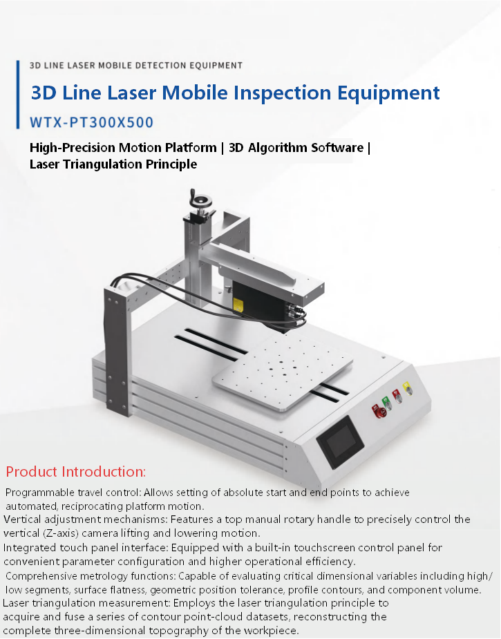
Some of the most interesting inspection platforms available now combine two or more sensing technologies in a single unit. A common configuration pairs a telecentric camera for fast 2D measurements with a laser profiler or touch probe for 3D features. Others integrate an optical head with an X-ray module for parts that need surface inspection and internal verification in the same cycle.
The appeal is obvious: fewer machines, less floor space, a single interface for operators to learn. But multi-sensor systems demand a more sophisticated operator and tighter environmental control. The calibration between different sensors must be maintained religiously, or the outputs drift relative to each other in ways that can mask real defects.
If your inspection needs genuinely span surface and internal or 2D and 3D on the same part, a multi-sensor system may simplify your workflow. If your mix of parts is highly varied, you might be better served by separate, specialized machines that each do one thing extremely well. There is no universal right answer—only the right answer for your particular production reality.
Bringing It Together Into a Selection Framework
When the time comes to compare specific inspection machines, try running each option through this simple filter:
- Defect coverage: Against your actual defect list, what percentage of known failure modes can this technology reliably detect?
- Speed compatibility: Does it match or exceed your line’s cycle time, including part handling?
- Operator reality: Can a trained operator run production recipes without daily vendor support?
- Data output: Does the machine produce traceable records you can use for audits and continuous improvement, or just a green/red light?
- Environmental fit: Will it survive your factory’s temperature, dust, and vibration levels without constant recalibration?
Weight these factors based on your specific pain points. A machine that scores perfectly on speed but poorly on defect coverage for your top failure mode is a bad investment, no matter how impressive its spec sheet looks.
A Practical Next Step
This decision process can feel heavy, especially when you’re balancing production pressure against capital investment timelines. But the clarity it forces is worth the effort. You’ll walk into vendor evaluations with a checklist that’s rooted in your own failure data, not someone else’s generic feature list.
If you’re at a stage where you want to survey what’s actually available—different machine types, sensing technologies, and configurations from a range of builders—having a curated starting point helps cut through the noise. Resources like InspectionMachinePro.com exist to give you that overview, so you can compare realistic options without days of scattered searching. No single machine fits every line, but knowing the landscape makes the right choice far easier to spot.
Leave a Reply