

In high-end manufacturing sectors such as consumer electronics, automotive smart cockpits, and semiconductor carrier substrates, glass has evolved from a passive protective layer into a core functional interface.
From chemically strengthened aluminosilicate glass to ultra-thin flexible display substrates, modern components demand extremely high standards of optical and structural integrity. Even a micron-level scratch (≈10 μm), a subsurface bubble, or a localized micro-fissure can lead to catastrophic failure during lamination, optical distortion in display systems, or spontaneous breakage under thermal stress.
However, glass inspection remains one of the most complex challenges in industrial machine vision. The combination of high transparency and strong reflectivity makes conventional 2D imaging unreliable, as light either passes through the material or reflects as strong glare that masks surface defects.
To achieve stable 100% inline inspection, manufacturers rely on advanced automated inspection machines built on polarization control, structured lighting, and phase-based optical reconstruction.
1. Mapping Critical Defect Modes in Precision Glass Manufacturing
Modern glass production involves multiple thermal, chemical, and mechanical processing stages. Defects may occur on the surface, at the edges, or within the internal matrix of the material.
A typical inspection flow is structured as follows:
[Raw Glass Cutting] ➔ (Edge Crack & Chip Detection) ➔ [Chemical Strengthening] ➔ [Surface Coating Process] ➔ (Scratch / Contamination Inspection)
Edge Micro-Cracks and Chipping
During cutting with diamond wheels or laser systems, localized stress concentrations generate edge micro-cracks and chipping defects.
If undetected, these micro-cracks propagate during chemical tempering or thermal cycling, significantly increasing the probability of spontaneous fracture in downstream assembly.
Subsurface Bubbles and Internal Inclusions
During float glass formation, microscopic gas bubbles (<0.05 mm) may become trapped inside the glass structure. These internal voids act as optical scattering centers, causing:
- Backlight distortion
- Uneven brightness distribution
- Display dead-zone artifacts
These defects are impossible to detect using conventional surface imaging alone.
Coating Voids and Surface Contamination
After polishing, glass is typically coated with anti-reflective (AR), anti-glare (AG), or anti-fingerprint (AF) layers.
Inspection systems must distinguish between:
- Permanent coating voids (critical defect)
- Temporary dust particles (non-critical contamination)
- Residual cleaning streaks
Misclassification at this stage directly affects yield efficiency.
2. Technical Matrix: Solving Transparency-Based Optical Failure
Transparent materials introduce unique imaging challenges because light behavior cannot be controlled using standard front-light illumination alone.
| Inspection Challenge | Optical Limitation | Advanced Vision Solution |
|---|---|---|
| Internal Bubble Detection | Low contrast within transparent medium | Dark-field laser line transmittance |
| Surface Scratch Detection | Strong specular reflection | Cross-polarized coaxial lighting |
| Flatness / Warping | 2D imaging cannot measure depth | Phase-measuring deflectometry |
Internal Defect Detection via Dark-Field Illumination
In dark-field optical inspection, light is injected from edge or bottom angles. Only defects scatter light into the camera, making internal bubbles appear as bright signals against a dark background.
This transforms transparency from a limitation into an advantage.
Surface Scratch Suppression via Polarization
On polished glass surfaces, reflected light becomes partially polarized. By using cross-polarization filters, unwanted glare is eliminated while preserving micro-level surface defects such as scratches and abrasions.
Flatness and Warp Measurement
Microscopic bending or warping is detected using structured optical projection systems, enabling measurement of surface deviation beyond traditional imaging limits.
3. Phase-Measuring Deflectometry for Sub-Micron Surface Reconstruction
For advanced applications such as automotive curved displays and semiconductor-grade glass wafers, surface flatness is a critical performance parameter.
Modern systems utilize Phase-Measuring Deflectometry (PMD), a non-contact optical metrology technique.
The process works as follows:
- A structured sinusoidal pattern (zebra stripes) is projected onto a reference screen
- The pattern reflects off the glass surface
- A high-resolution camera captures the distorted reflection
- Phase-shift algorithms reconstruct a full 3D surface map
If the glass is perfectly flat, the reflected pattern remains geometrically stable. Any micro-deformation causes measurable phase deviation.
This allows detection of surface distortion down to nanometer-level resolution, depending on system configuration.
4. Industrial Deployment Considerations for Glass Inspection Systems
Deploying a high-performance automated glass inspection machine requires precise alignment between optics, motion control, and environmental stability.
Key engineering constraints include:
- Dust isolation within optical tunnels
- Stable polarization alignment calibration
- Thermal drift compensation in imaging systems
- High-speed defect classification under continuous motion
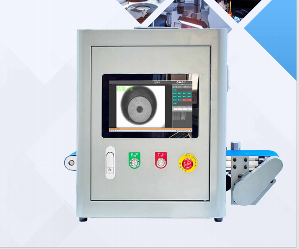
To reduce integration complexity, many manufacturers adopt turnkey optical platforms such as those developed by specialized industrial providers like InspectionMachinePro. These systems integrate:
- Pre-calibrated deflectometry modules
- Dust-shielded optical enclosures
- Deep learning-based defect classification engines
- Recipe-driven production switching interfaces
This significantly reduces deployment time and engineering risk in high-volume production environments.
5. Frequently Asked Questions (FAQ)
Q1: Why are polarization filters essential in glass inspection systems?
Polarization filters eliminate specular reflections caused by polished glass surfaces. By aligning filters perpendicular to reflected light polarization, systems suppress glare and enhance visibility of micro-scratches and subsurface defects.
Q2: What is the difference between bright-field and dark-field glass inspection?
- Bright-field inspection: Defects appear as dark disruptions against a bright background
- Dark-field inspection: Clean glass appears dark; defects scatter light and appear bright
Each method is optimized for different defect types.
Q3: Can curved glass panels be inspected with the same system?
Yes. Curved glass inspection is achieved using either:
- Multi-axis robotic camera positioning systems
- CAD-referenced multi-camera arrays
- 3D surface compensation algorithms
These approaches ensure accurate inspection across non-planar geometries.
Conclusion
In precision glass and touch panel manufacturing, defect control is fundamentally tied to optical physics and surface metrology. Traditional imaging methods are no longer sufficient to guarantee yield stability in modern production environments.
By integrating automated inspection machines equipped with polarization control, dark-field illumination, and phase-measuring deflectometry, manufacturers can achieve consistent detection of both surface and subsurface defects.
This transition transforms quality assurance from a reactive checkpoint into a continuous precision control system, ensuring higher yield rates, reduced material waste, and long-term product reliability in advanced display and optical industries.
Leave a Reply